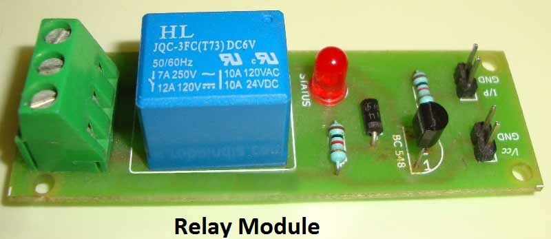
Alternatively the relay circuit can be built as per the circuit diagram. Remote controlled on off switch circuit.

Sw 4867 Volume Remote Control Circuit Diagram
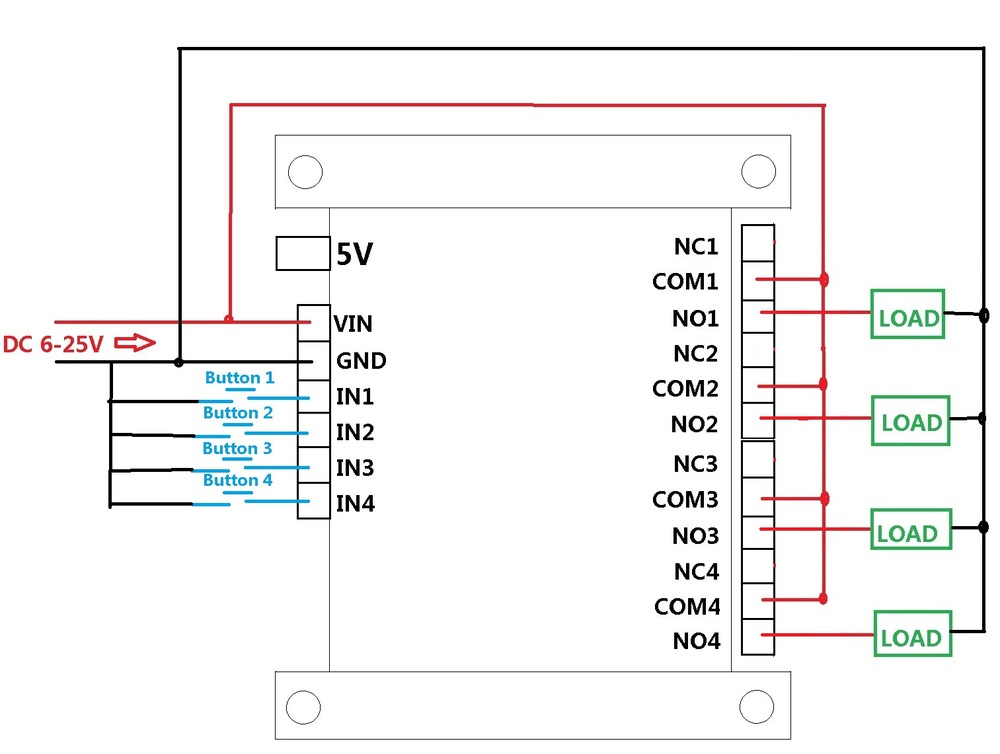
Remote control switch circuit diagram. A wiring diagram is a simplified standard photographic depiction of an electrical circuit. A relay switch is used at the output of the circuit which can be connected with the appliances to make them switch onoff. A 4 channel relay module is used in this project in order to control the light. 3 way switched outlet wiring. In this diagram two 3 way switches control a wall receptacle outlet that may be used to control a lamp from two entrances to a room. The circuit has also a good range of upto 20 meters.
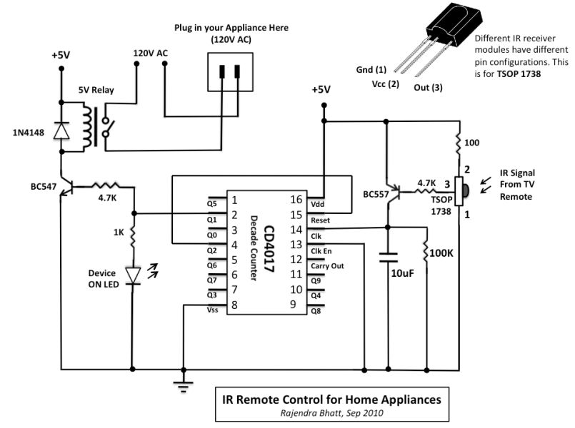
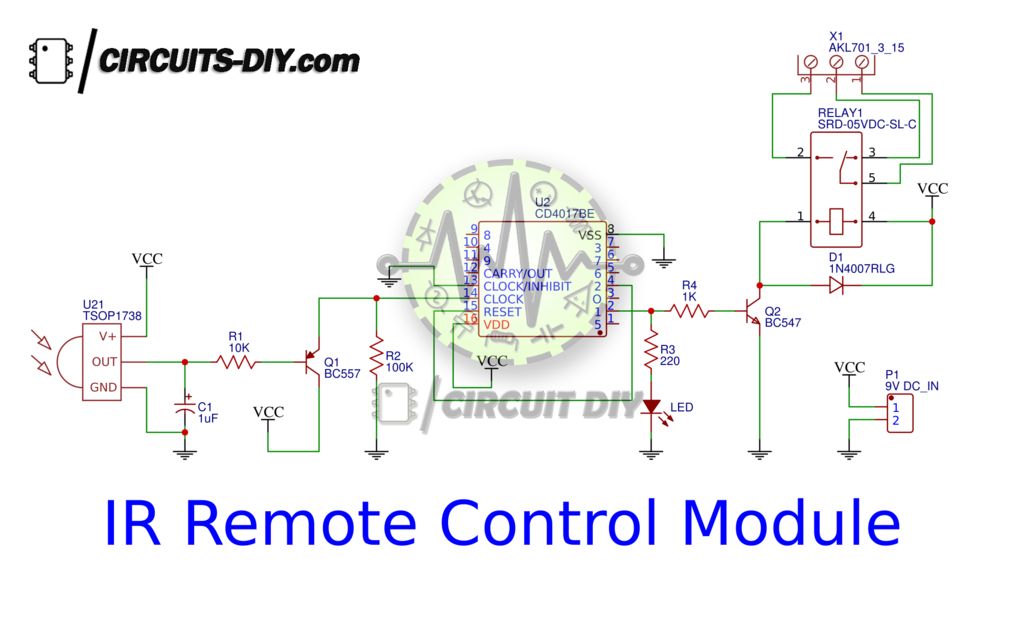
In the receiver section there are 3 photodiodes which will detect the infrared signals from the receiver and produce leakage current to the capacitor c1. Remote controlled switch circuit diagram notes. We have used ic 4017 to convert it into a push on push off switch. For good results use a good quality fm transmitter with the circuit. Remote controlled switch this is the very simple circuit diagram of ir remote control switch. Variety of yamaha outboard ignition switch wiring diagram.
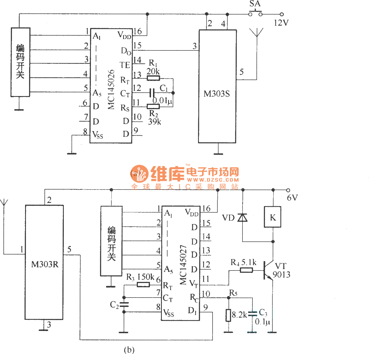
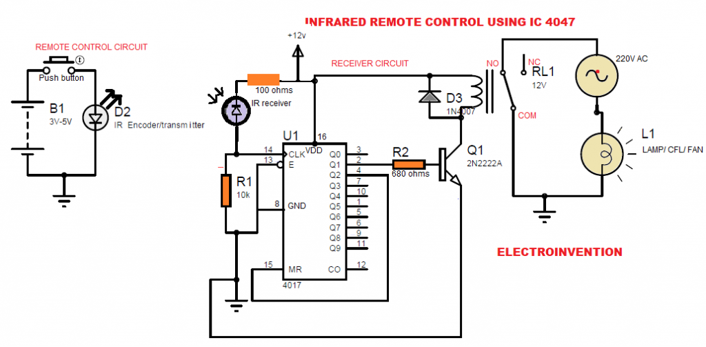
The whole project contains two parts which is an fm transmitter and a rf receiver. Three wire cable runs between the switches and the outlet. Receiver circuit is connected to ac appliance via relay so that we can control the light remotely. It shows the parts of the circuit as streamlined forms and also the power and signal connections in between the tools. You can on or off any appliance by this circuit ie fan light etcthis is works upto 5 10 m lenght from remote. This current is given to the inverting input of 3130 ic which will get triggered by this current and give amplified output.
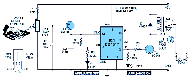
In this remote controlled switch circuit we are using tv remote to onoff the ac light by pressing any button of remote and using the tsop1738 at receiver end. A single channel relay board is sufficient. This circuit is wired the same way as the 3 way lights at this link. We uses normal switch in our daily life and after a long time used to these swithing system we can no more interested in that. Before wiring the circuit make sure that the carrier frequency of the tv remote you have is 38 khzfor that wire the sensor part only point your remote to the tsop1738 and press any switchif out put of tsop1738 goes low then ok your remote is of 38khz typenothing to worry almost all tv. Remote controlled switch for home appliance.
Hunter ceiling fan wiring diagram switch with remote control harbor breeze ceiling fan wiring capacitor diagram how to ceiling fan switch wiring criacuervos info 3 way wiring ceiling fan with remote for two wire hookup ceiling fan wiring colors davestevensoncpa com tx29 remote control for ceiling fan user manual hunter fan. Circuit diagram of infrared remote control switch. The circuit works by pressing any key on the remote it can also operated manually by pressing switch s1 to on state. A simple ir led with 38 khz pulse can be used as a remote control. Circuit design of remote controlled light switch. Yamaha outboard wiring diagram inspirational yamaha 703 remote.
Gallery of Remote Control Switch Circuit Diagram